-40%
12V 4 Channel Delay Relay Shield Board Cycle Timer Switch Module PLC Smart Home
$ 9.07
- Description
- Size Guide
Description
Product DescriptionProduct Name:
12V 4 Channel Delay Relay Shield Board Cycle Timer Switch Module PLC Smart Home
Modules No:
CE007
Package inlcuded:
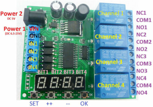
1 PCS DC 5V 9V 12V 24V 4 channel multi-function delay relay board
Product Features:
Longest delay time : 00h:00m:01s - 99h:59m:59s
4 channel relay,each channel independently triggered independent delay, do not interfere with each other.
6 kinds of functional modules,
each functional module has three sub-modes
(no cycle, 2-99 cycle, always cycle).
Input optical isolation.
Power anti-reverse diode.
High Q value SMD electrolytic capacitors.
Product Specifications:
1 Operating voltage: power supply 1,DC 6.5-25V; power supply 2,DC 5V
2 Operating Current(DC 12V): Standby current (all relays closed) 16MA, 1 relay open 50MA, 2 relays open 82MA, 3 relays open 115MA, 4 relays open 150MA
3 Size: 80x66x20
4 Weight : 75g
5 Relay maximum load capacity: DC 1-100V/6A; AC 85-265V/5A
Typical applications:
1 DC 6-25V control circuit,Wiring diagram below. "LOAD" may be LED lights, fans, motors and
2 DC 5V control circuit,Wiring diagram below. "LOAD" may be LED lights, fans, toy car and
User Instructions:
Short press: press key time is less than 2 seconds;
Long press: press key time more than 2 seconds;
Status: working status , set status, power-saving status.
working status : start work after powering. Displays the remaining time of 1 channel, the parameters can be displayed the "channel select" to set;
Set status: short press the "SET" key to enter "channel select" Status. Short press "OK" button to exit the setting;
power-saving status: in this Status,digital tubes donot display,and other features work correctly. Long press "OK" button after 5 seconds to enter power-saving status, press again "OK" button for 5 seconds or re-power to exit power-saving status.
Factory settings: press and hold "++" and "--" two button for 3 seconds, to restore factory settings, and the digital tube will turn open . After re-power , will run default parameters.
Settings:
1.After power , the remaining time of digital display channel (default channel 1).
2.Press "SET" button to enter "channel select" interface. In the "channel select" screen, then press "++"/"-" button to select channel to operate (relay). Press "OK" button will exit "channel select" screen, and save the current parameters. Press "SET" button into "parameter settings" interface.
3. under "parameters" screen press "SET" button you can switch parameters. "++"/"-" Button to modify the parameters. Press the "OK" button to exit the "parameters" screen, and save the current parameters.
"channel select" interface:
"parameter settings" interface:
Timer T1 T2 time minimum unit is second, so the timing range of T1 T2 is 99 hours 59 minutes 59 seconds.
The number of cycles(Nx) is the number of cycles to perform an action triggered once(Nx = 00 indicates always cycle, Nx = 01 means no cycle).So you can set Number of cycles is: 1-99 times or always cycle.
Noun resolved:
NO : Relay normally open contact
COM : Relay common contact
NC : Relay normally closed contact
Relay open : COM connect NO.
Relay close : COM disconnect NO.
.
Function Mode:
The following Function Modes can be set to cycle mode operation.You can set Number of cycles (Nx 1~99 times,00 is always cycle, the default is 01 not cycle).
F0: After power-up, the relay
close
. Trigger input (IN1/2/3/4), relay
open
. T1 time delay
close
.
F1: After power-up, the relay
open
. Trigger input , relay
close
. T1 time delay
open
.
F2: After power-up, the relay
close
. Trigger input , delay time T1 and relay
open
. T2 time delay relay
close
.
F3: After power-up, the relay
open
.Trigger input , delay time T1 and relay
close
. T2 time delay relay
open
.
F4: After power-up, the relay
close
. After the delay time T1 and relay
open
. T2 time delay relay
close
.
F5: After power-up,the relay
open
. After the delay time T1 and relay
close
. T2 time delay relay
open
.
